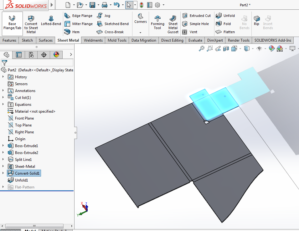
Create new bodies in an existing sheet metal part using base flange convert to sheet metal insert bends and lofted bend commands.
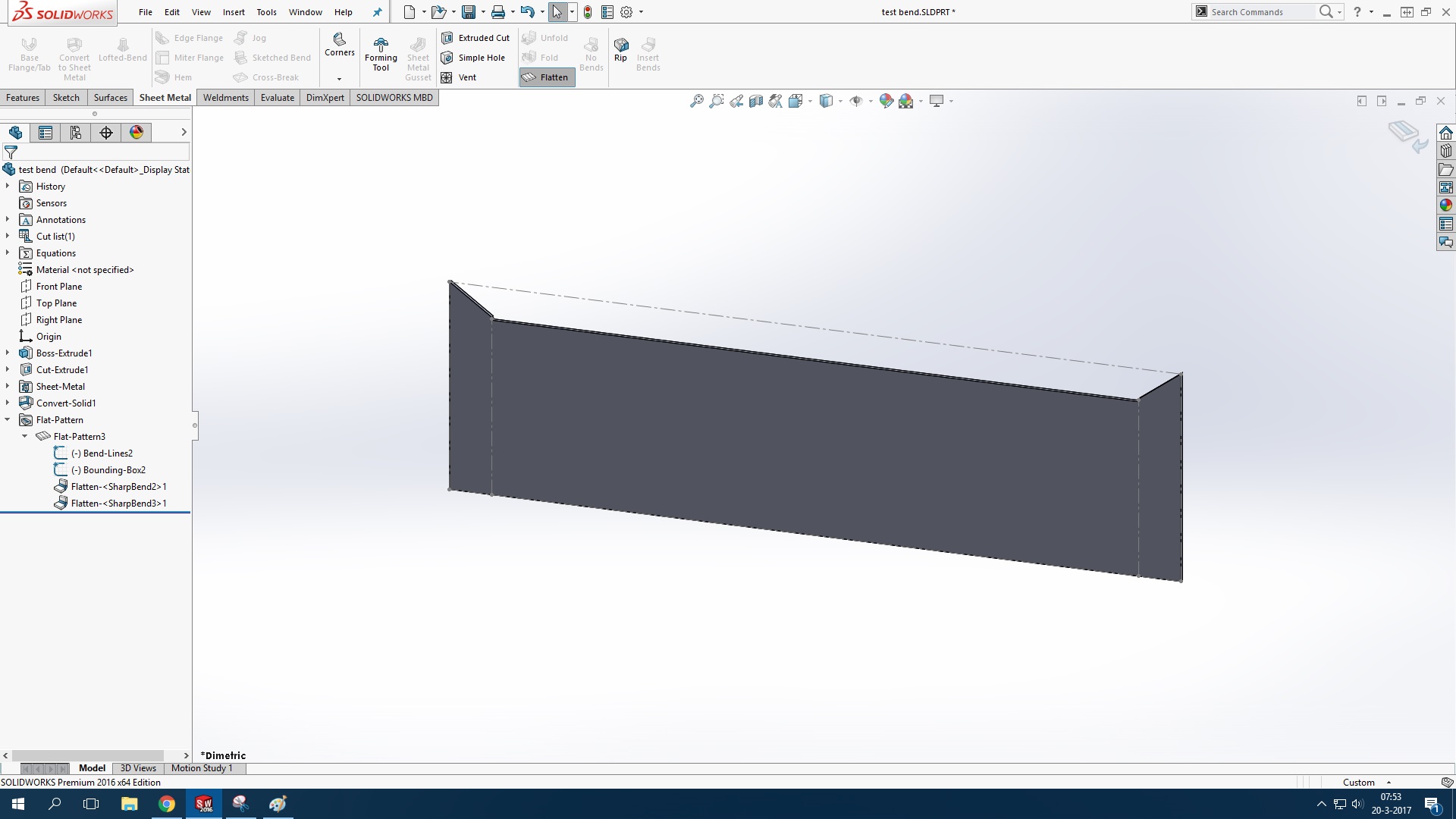
Solidworks turn solid to sheet metal with multiple bend radius.
Solidworks 3d allows you to quickly create sheet metal part designs using a simple design process saving you time and development costs thanks to specific sheet metal features.
When cleared the body is consumed by the convert to sheet metal feature.
Solidworks how to create a simple sheet metal part in solidworks.
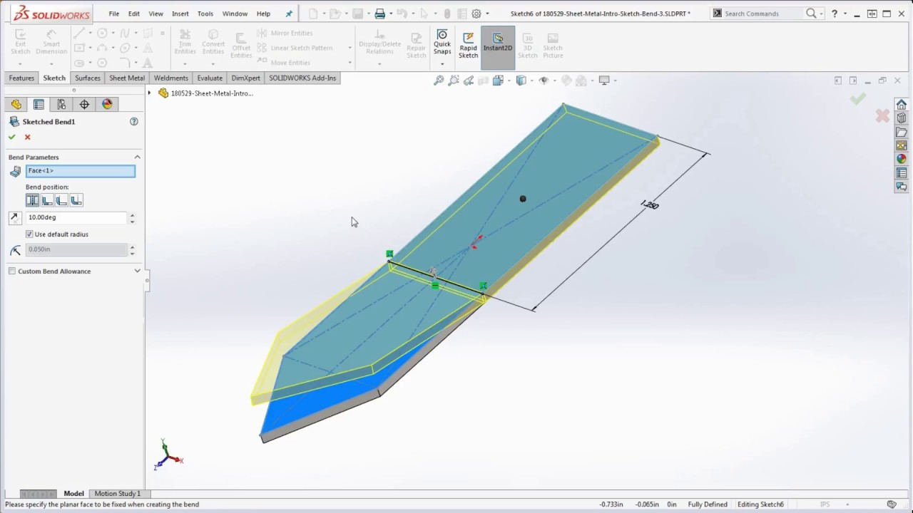
A quick tour and introduction using the solidworks sheet metal sketch bend feature.
Under bend allowance select from.
It is one of the main and basic forms of metal working.
For some reason i couldn t get my mirrored bends to flatten so i redid that as a couple of edge flanges.
In the featuremanager design tree right click sheet metal and click edit feature.
The greatest feature of sheet metal is that it s having ability to be formed and shaped by no of process.
Under bend edges select the model edges that will form bends.
Select another value for the bend radius.
We will focus on the flange method where a sheet metal part is created in the formed state using specialized sheet metal features.
Set the sheet thickness and default bend radius.
Bend table k factor bend allowance bend deduction or bend calculation.
Split a single sheet metal part into multiple bodies.
Click a face or edge on the model for fixed face or edge the fixed face remains in place when the part is flattened.
In the new feature s propertymanager clear use default radius and select use gauge table.
I attached a 2014 file.
Sheet metal is the metal formed into thin and flat pieces which uses sheets of thickness less than 6 mm.
Looks like everything lines up with your file.
Set a value for bend radius.
In the propertymanager under bend parameters.
Add another sheet metal feature to the part.
I also changed you bend radius a bit in order to lessen the gap on the welded edge.
Under sheet metal gauges select use gauge table and select a table.
We can use these features to create sheet metal designs with several different methods.
Select a face as the fixed face for the sheet metal part.
You can cut or bend into various shapes using sheet metal.
Insert one or more sheet metal weldment or other bodies into an existing sheet metal part.
To create a multibody sheet metal part.
In the base flange propertymanager under sheet metal gauges select use gauge table and then select a table.
Click insert bends sheet metal toolbar or insert sheet metal bends.